The Making of Excursion Funnel
 Alain Galvan ·9/4/2016 8:30 PM · Updated 4 months ago
The making of my Shadertoy Siggraph 2015 Entry 'Excursion Funnel'.
Tags: blogshadertoyraymarching
Alain Galvan ·9/4/2016 8:30 PM · Updated 4 months ago
The making of my Shadertoy Siggraph 2015 Entry 'Excursion Funnel'.
Tags: blogshadertoyraymarching
Whenever I think of Portal 2, there's a ton of amazing memories that come to mind, the science fair, Wheatley's incompetence, Spaaaaaaaaaaaaaaaaaaaaaaaccee. I wanted to make a shader that showcased one of my favorite scenes, the tractor beam leading to Wheatley.
Nothing is born from a vacuum, so it's thanks to all the resources posted by ShaderToy users like iq and mplanck that this was possible, a lot of the code here was forked from them, alteredaquila, the three.js team such as mrdoob, unity's standard shaders.
Note: to view the shader at it's best settings, you'll have to set your browser to render on your dedicated gpu. This can be done in chrome with the latest Nvidia drivers by right clicking chrome > Run With Graphics Processor > Your GPU.
Here's the final program in action:
Shadertoy requires that your entire program be written as a GLSL shader, rather than using other aspects of WebGL such as Vertex Buffers, Frame Buffer Attachments, etc. This isn't too much of a problem, as the community has been using a real-time gpu raycasting algorithm called *Raymarchingan alternative to triangles [Quilez 2008] .
"The idea: draw two triangles that cover the entire screen area, and invoke a pixel shader that will create an animated or static image." ~ Iñigo Quilez, Rendering Worlds with Two Triangles with raytracing on the GPU
The idea is that you can describe any volume as a density function [Quilez 2008], for example:
float sphere( vec3 p, float r )
{
  return length(p) - r;
}
p is a domain of points in (R^3) space, and (r) is just the radius of a sphere. So say (p) is vec3(0.0), and (r) is 1., the function will return -1, but if (p) is say vec3(4.0) the returned value is greater than 0.
To translate the sphere, you just need to subtract (p) by a vec3 with the position you would like it to be.
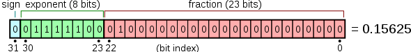
By having density be defined as a floating point value instead of a bool, you can define a range of values to be whatever you want, all values (x \leq 0) are opaque, all positive are empty (So using the sign bit behaves like a bool).
You can say, have the density function behave like a gas, where any value above 1 is solid, but any between 1 and zero can have different densities for say, clouds. This is used in IQ's Clouds shader as a means of changing the output color:
vec4 integrate(in vec4 sum, in float dif, in float density, in vec3 bgcol, in float time)
{
  //Colors
  vec3 gray = vec3(0.65);
  vec3 lightgray = vec3(1.0, 0.95, 0.8);
  vec3 bluegray = vec3(0.65, 0.68, 0.7);
  vec3 orangegray = vec3(0.7, 0.5, 0.3);

  //Density Colors
  vec4 col = vec4(mix(1.15 * lightgray, gray, density), density);
  vec3 lin = (1.3 * bluegray) + (0.5 * orangegray * dif);
  col.xyz *= lin;
  col.xyz = mix(col.xyz, bgcol, 1.0 - exp(-0.003 * time * time));

  //Front to Back Blending
  col.a *= 0.4;
  col.rgb *= col.a;
  return sum + col * (1.0 - sum.a);
}
Raymarching is a method of GPU raytracing, with the goal of trying to compute or estimate a lower bound of the distance to the closest surface at any point in space. It works by iterating over discrete steps until that ray collides with an object.
#define MARCH_STEPS 64

float raymarch(vec3 rayOrigin, vec3 rayDirection, float mind, float maxd)
{
  // Starting integrated distance
  // This number approaches the scene function's distance value
  float dist = 10. * epsilon;

  // Final distance Value
  float t = 0.;

  // March
  for (int i = 0; i < MARCH_STEPS; i++)
  {
    // Near/Far Planes
    if (abs(dist) < mind || t > maxd)
      break;

    // Advance the distance of the last lookup
    // as each step occurs `dist` approaches values below 0.
    // resulting in the final distance `t`.
    t += dist;
    dist = scenedf(rayOrigin + t * rayDirection);
  }

  // We return the ray's collision distance and any relevant sample data.
  return t;
}
You can create a camera by defining a system that determines the direction of each ray casted.
//Globals
vec3 g_camPointAt = vec3(0.0, 0.0, 0.0);
vec3 g_camOrigin = vec3(0.0, 0.0, 0.0);
float g_fov = 0.7;

//Camera Data
struct Camera
{
  vec3 origin;
  vec3 direction;
};

Camera setupCamera(vec2 fragCoord)
{
  // aspect ratio
  float invar = iResolution.y / iResolution.x;
  vec2 st = fragCoord.xy / iResolution.xy - .5;
  st.y *= invar;

  // calculate the ray origin and ray direction that represents
  // mapping the image plane towards the scene
  vec3 iu = vec3(0., 1., 0.);
  vec3 iz = normalize(g_camPointAt - g_camOrigin);
  vec3 ix = normalize(cross(iz, iu));
  vec3 iy = cross(ix, iz);

  vec3 direction = normalize(st.x * ix + st.y * iy + g_fov * iz);

  Camera camera;
  camera.origin = g_camOrigin;
  camera.direction = direction;

  return camera;

}
The camera is built to be first person, and works by transforming the pointing vector with mouse uniforms.
void animateCamera()
{
    g_camOrigin = vec3(0., 1.68, 0.);

    //Map click to [-.8, .8].
    vec2 click = iMouse.xy / iResolution.xx;
    click = 1.6 * click - .8;

    float yaw = PI_OVER_TWO * (click.x);

    g_camPointAt = camOrigin + vec3(cos(yaw), 0., sin(yaw) );
}
In main(), these functions are used as so:
#define RAYMARCH_MAXDIST 50.0

// Setup Camera
CameraData cam = setupCamera(fragCoord);

//Animate Camera
animateCamera();

// Scene Marching
vec2 scenemarch = distmarch(cam.origin, cam.direction, RAYMARCH_MAXDIST);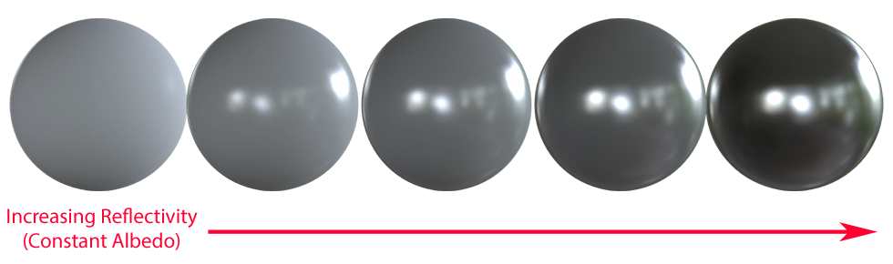
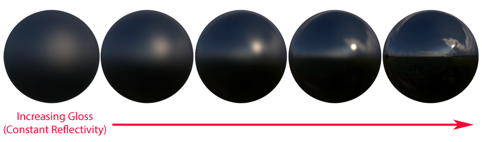
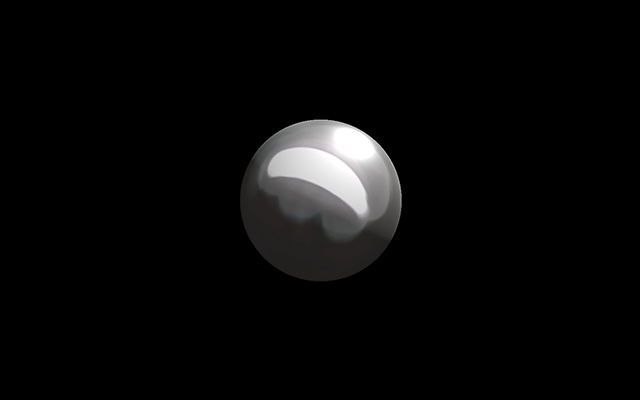
Physically Based Rendering is a method of describing materials that decouples a material's behavior from it's color [Russell 2015]. A material's defined as:
Albedo - base color, what the color of a surface would be in a perfectly ambient environment.
Metallic - How reflective a material is.
Roughness - how rough a material is (Unreal calls this roughness, Unity calls this smoothness, others call it gloss or microsurface)
In this example I'm using PBR rendering to quickly design materials via this struct:
struct SurfaceData
{
  vec3 point;
  vec3 normal;
  vec3 basecolor;
  float roughness;
  float metallic;
};
The materials are part of certain ranges:
// MATERIAL DEFINES
#define POTATO_MATL 1.
#define REDPLASTIC_MATL 2.

//inout means mutating surf
void material(float surfid, inout SurfaceData surf)
{
  vec3 surfcol = vec3(1.0, 1.0, 1.0);
  if (surfid - .5 < SPHERE_MATL)
  {
    surf.basecolor = vec3(0.8, 0.2, 0.5);
    surf.roughness = 0.5;
    surf.metallic = 0.8;
  }
  else if (surfid - .5 < REDPLASTIC_MATL)
  {
    surf.basecolor = vec3(0.0, 0.0, 0.0);
    surf.roughness = 1.0;
  }
  // Continue if you have more materials...
}
In main() the function is used as so:
#define INITSURF(p, n) SurfaceData(p, n, vec3(0.), 0., 0.)

vec3 mp = cam.origin + scenemarch.x * cam.dir;
vec3 mn = calcNormal(mp);
SurfaceData currSurf = INITSURF(mp, mn);
material(scenemarch.y, currSurf);
scenecol = shadeSurface(currSurf);
Shadows are raymarched the same as volumes, however the rayOrigin and Direction are the surface point and the light direction respectively.
#define SOFTSHADOW_STEPS 40
#define SOFTSHADOW_STEPSIZE .1

float calcSoftShadow( vec3 rayOrigin, vec3 rayDirection, float mint, float maxt, float k )
{
  float shadow = 1.0;
  float t = mint;

  for( int i = 0; i < SOFTSHADOW_STEPS; i++ )
  {
    if( t < maxt )
    {
      float h = scenedf( rayOrigin + rayDirection * t ).x;
      shadow = min( shadow, k * h / t );
      t += SOFTSHADOW_STEPSIZE;
    }
  }
  return clamp( shadow, 0.0, 1.0 );

}
Ambient occlusion is calculated by marching on a point's normal several times. darker regions will be in areas that are close to the original point p.
#define AO_NUMSAMPLES 8
#define AO_STEPSIZE .1
#define AO_STEPSCALE .4

float calcAO( vec3 p, vec3 n )
{
  float ao = 0.0;
  float aoscale = 1.0;

  for( int aoi = 0; aoi < AO_NUMSAMPLES; aoi++ )
  {
    float step = 0.01 + AO_STEPSIZE * float(aoi);
    vec3 aop =  n * step + p;

    float d = scenedf( aop ).x;
    ao += -(d - step) * aoscale;
    aoscale *= AO_STEPSCALE;
  }

  return clamp( ao, 0.0, 1.0 );
}Shaders can do some amazing things extremely efficiently, from volumetric rendering to advanced lighting techniques like PBR. Keep working and make something amazing!
| [Quilez 2008] |
| [Quilez 2008] |
| [Russell 2015] |